
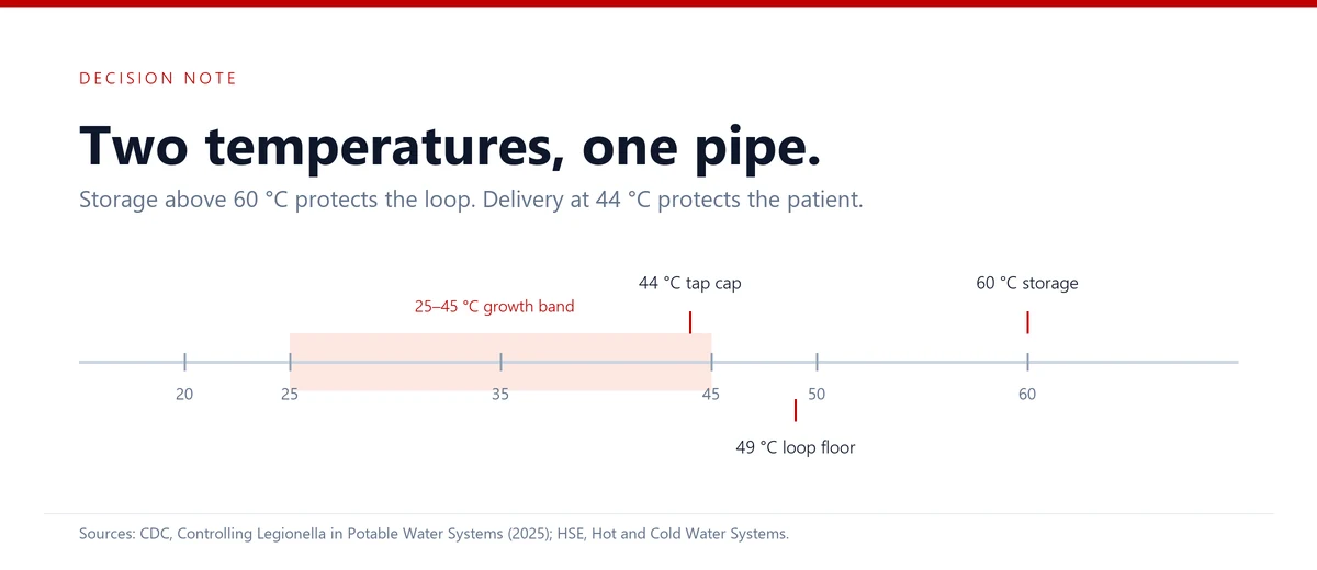
Two temperature numbers govern Legionella control in a hospital, and they pull in opposite directions. Water must be stored hot enough to suppress the organism, and it must reach the tap cool enough that a patient cannot be scalded. The United States Centers for Disease Control and Prevention sets the storage figure above 60 °C (140 °F) and asks that circulating hot water never fall below 49 °C (120 °F) (“Controlling Legionella“). The United Kingdom Health and Safety Executive sets the same 60 °C storage figure and then asks the water to reach 50 °C at the outlet, or 55 °C in healthcare premises, within one minute (“Hot and Cold Water Systems”). Neither body asks for 60 °C at the tap, because 60 °C at the tap is a burn.
The distance between those two numbers is therefore deliberate. It is also the part of a building water system where Legionella control is usually lost, because every component that closes that distance — the mixing valve, the dead leg, the low-flow sensor tap, the carbon filter, the softener — sits downstream of the heat source.
This article works through that gap as an engineering problem rather than a compliance one. It compares what the two guidance documents actually require, identifies where the requirements collide inside a real distribution loop, and sets out the verification points that show whether the design still works two years after handover.
1. What the two guidance documents actually require
The two documents were written for different building stocks and different regulatory cultures, so their numbers diverge in ways that matter at the drawing board. The CDC module is a toolkit for building water management programs and states that it exists to implement control measures “per ASHRAE Guideline 12” (“Controlling Legionella“). The HSE page describes the traditional UK temperature regime and points to HSG274 for the technical detail. Read side by side, they agree on storage and disagree, usefully, on delivery.
| Parameter | CDC guidance | HSE guidance | Where it lands in a design |
|---|---|---|---|
| Hot water storage | Above 60 °C (140 °F) | At least 60 °C | Calorifier setpoint, high-limit cut-out, legionella cycle schedule |
| Hot water circulation | Not below 49 °C (120 °F); recirculate continuously where possible | Reach 50 °C at outlets, 55 °C in healthcare premises, within one minute | Return-leg sensor becomes the controlling instrument, not the tank sensor |
| Cold water | Store and circulate below the 25–45 °C favourable range; growth possible from 20 °C | Below 20 °C where possible | Cold-side temperature control is often unachievable in warm climates |
| Scalding limit | Thermostatic mixing valves close to fixtures, which permits circulation above 49 °C | Risk above 44 °C; Type 3 valve where vulnerable users reach baths and showers | Valve position, not valve existence, decides whether the loop stays hot |
| Dead legs | Eliminate them; flush low-flow runs and dead legs at least weekly | Identified as a design and inspection item in HSG274 | Pipe layout at design stage; flushing record at operation stage |
| Disinfectant residual | Detectable throughout the system, as directed by the water management program | Alternative control where temperature is not the primary measure | Sampling points and re-dosing points, both of which cost money |
One reading of that table is that the UK regime is stricter, because 55 °C in healthcare premises is hotter than a 50 °C general target. The more useful reading is that the two regimes protect against different failure modes. The CDC numbers describe a system that keeps the organism from multiplying in storage and in the loop. The HSE numbers describe a system that also proves the temperature survives the journey to the outlet, which is why the one-minute clause appears at all.
2. The mixing valve sits exactly where the requirements collide
A thermostatic mixing valve takes hot and cold water and delivers a blended stream at a fixed temperature. In a hospital the blend is set low, because the HSE page states that scalding risk begins where water leaves a tap above 44 °C, and that a Type 3 valve must cap the discharge at 44 °C where vulnerable people can reach baths or showers (“Hot and Cold Water Systems”).
That requirement creates a physical fact worth stating plainly: the water leaving a correctly set mixing valve is at 44 °C, and 44 °C sits inside the 25–45 °C band that the CDC identifies as favourable to Legionella growth (“Controlling Legionella“). The blended water is not itself a hazard, because it is normally flowing. It becomes one when it stops, which is what happens in the branch that serves a single hand basin in a room that is used twice a week.
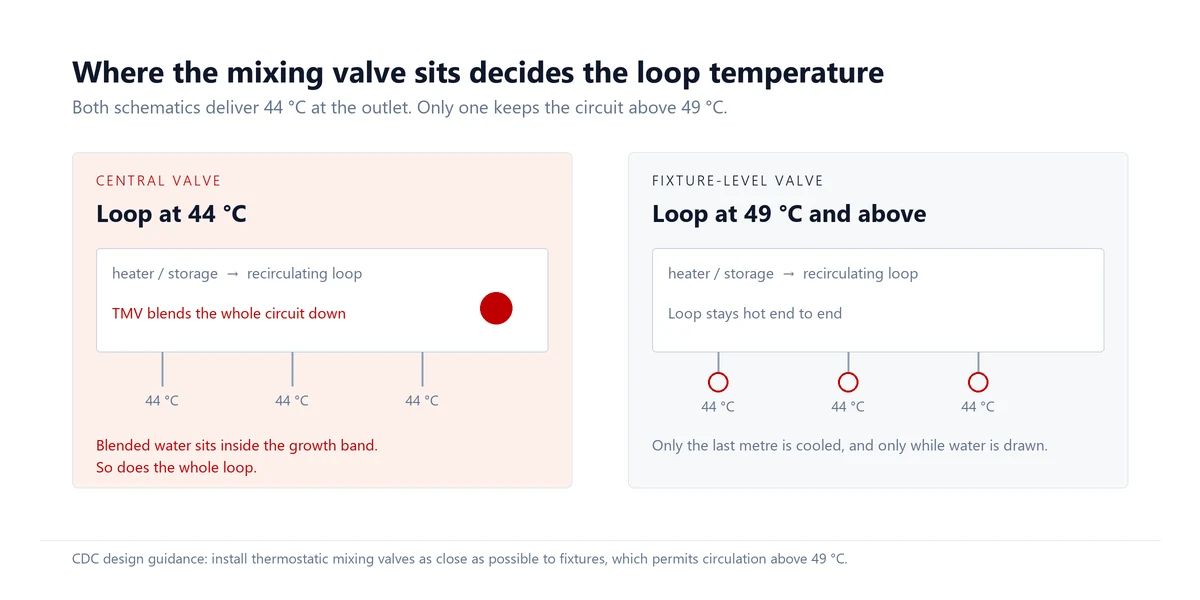
The CDC resolves this tension by position rather than by temperature. Its design guidance asks for mixing valves “as close as possible to fixtures”, and gives the reason explicitly: close-coupled valves allow circulating hot water to stay above 49 °C (“Controlling Legionella“). A single central mixing valve achieves the same outlet temperature and destroys the loop, because it cools the entire distribution circuit into the growth band. A valve at each fixture keeps the loop hot and cools only the last metre.
The maintenance consequence follows the same logic. The CDC lists thermostatic mixing valves among the components that must be cleaned and maintained regularly, alongside aerators, showerheads, hoses, filters and storage tanks. A valve that is never serviced drifts, and a drifted valve either scalds a patient or quietly over-cools a branch.
3. The cold side fails first in warm climates
Cold water looks like the easy half of the problem, and in temperate buildings it usually is. The HSE asks for cold water below 20 °C where possible, and the CDC asks for storage and circulation below the 25–45 °C favourable range while noting that growth may occur as low as 20 °C (“Hot and Cold Water Systems”; “Controlling Legionella“). Both targets assume the incoming mains water is cooler than the building.
That assumption does not survive everywhere. In many of the markets where hospital water plants are now being built, summer mains temperatures approach or exceed the bottom of the growth band, and a cold storage tank in an unconditioned plant room can sit inside it for months. Once the temperature argument fails, three controls carry the risk instead: water age, disinfectant residual and biofilm management. The CDC names exactly those factors — sediment and biofilm, temperature, water age and disinfectant residual — as the ones that affect growth (“Controlling Legionella“).
A design that assumes cold-side temperature control, in a climate that cannot deliver it, has not made a conservative choice. It has removed the only barrier it was relying on and left the other three unmanaged.
4. Treatment equipment can quietly remove the residual you are counting on
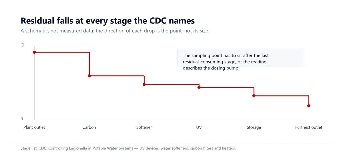
This is the part of the problem that belongs to the water treatment engineer rather than the building services engineer. The CDC asks designers to “identify water system components that speed the decay of disinfectant residuals”, and then names four: UV devices, water softeners, carbon filters and heaters (“Controlling Legionella“). Every one of those four is a normal, necessary part of a hospital water plant. The issue is not that they are present, but that their position relative to the sampling point is rarely drawn.
| Component | Effect on the residual | Design response |
|---|---|---|
| Carbon filter (GAC) | Named by the CDC among components that speed residual decay; carbon removes oxidants by design | Place carbon where its removal is wanted, and re-dose or re-sample downstream of it |
| Water softener | Named by the CDC among components that speed residual decay | Sample at the outlet, not at the plant discharge; log residual before and after the softener |
| UV device | Named by the CDC among components that speed residual decay | Treat UV as a point barrier; it leaves no residual, so it cannot protect the loop |
| Heaters and storage | Named by the CDC among components that speed residual decay | Size tanks for turnover and fit recirculating pumps, as the CDC’s design guidance asks |
| Point-of-use filter | No system-wide effect; protects only the fixture it serves | Specify 0.2 µm or finer and compliance with ASTM F838, as the CDC requires |
The practical rule that follows is simple and often ignored: the residual specification must be written at the point where the water is used, not at the point where it is dosed. A plant that doses chlorine to 0.5 mg/L at the outlet of a carbon filter and measures the same 0.5 mg/L three metres later has measured its own dosing pump, not the distribution system.
Kertone’s monitoring systems exist for exactly this reason. The Smart i total chlorine and hardness monitoring system automates sampling and titration on the dialysis-water pretreatment side, which is where a residual failure is both most likely and least visible to the operator.
5. Water age: the part of the design nobody inspects
Temperature and residual are measured. Water age is inferred, which is why it is the most common finding in a Legionella investigation. The CDC treats it as a first-order factor and gives two instructions: eliminate dead legs, defined as “sections of no- or low-water flow”, and flush low-flow piping runs and dead legs at least weekly (“Controlling Legionella“).
Both instructions are cheap at design stage and expensive afterwards. A capped tee left in place during a fit-out becomes a permanent weekly task, and the task survives only as long as the person who owns it. The CDC’s parallel warning about fixtures is worth reading alongside it: low-flow and mechanically complex outlets such as electronic sensor faucets carry their own risk, because they combine small volumes with long idle periods.
The verification table below converts the guidance into instrument readings. It is deliberately short, because a monitoring plan that a shift team cannot complete is not a monitoring plan.
| Sampling point | Parameter | Control target | Frequency |
|---|---|---|---|
| Calorifier outlet | Temperature | Above 60 °C | Continuous, logged |
| Return leg, furthest point | Temperature | Not below 49 °C | Continuous, logged |
| Sentinel outlet, hot | Temperature | 50 °C within one minute; 55 °C in healthcare premises | Monthly, recorded |
| Sentinel outlet, cold | Temperature | Below 20 °C where achievable | Monthly, recorded |
| Mixed outlet after TMV | Temperature | 44 °C maximum | At commissioning, then on service |
| Building entry and furthest outlet | Disinfectant residual | Detectable, per the water management program | Weekly to monthly |
| Dead legs and low-flow branches | Flushing record | At least weekly | Weekly, signed |
6. What the designer fixes and what the operator inherits
The split between the two is unusually clean in this topic, and the CDC’s design list maps onto it almost line by line. Insulation, dead-leg elimination, valve position, tank sizing with recirculating pumps and sampling ports are all decisions taken before concrete is poured (“Controlling Legionella“). Temperature logging, flushing, residual checks and the cleaning of valves, aerators, showerheads, hoses, filters and tanks are all decisions taken afterwards, every week, by someone who did not attend the design meeting.
A hospital water plant that is designed for the first list and commissioned without the second will fail slowly and invisibly. That is the argument for treating the monitoring hardware as part of the water system rather than as an instrument package bolted on at the end. The hospital water solutions that Kertone builds follow that sequence, with the distribution loop and its sampling points treated as part of the plant scope.
7. Remediation is a response, not a control strategy
When a positive sample appears, the temptation is to treat the system and close the case. The CDC is unusually direct about why that does not work. It states that thermal shock of water systems is not recommended, citing frequent failure and rapid recolonisation, and that chemical shock can control the organism but requires professional input, may need permitting, and does not solve the underlying conditions (“Controlling Legionella“). Its summary sentence is the one worth repeating to a client: after a successful remediation, the organism will likely recolonise if the conditions that supported growth are still present.
Point-of-use filters are the other tool that gets over-used. The CDC supports them where they are integrated into a water management program, at 0.2 µm or finer and compliant with ASTM F838, and then adds the limitation that matters: a point-of-use filter protects the fixture it is attached to, not the system behind it.
8. A commissioning checklist that survives handover
The list below is what distinguishes a system that passes commissioning from one that still passes an audit three years later. Each row corresponds to a requirement cited above, restated as something that can be checked on site.
| Check | Pass condition | Evidence to keep |
|---|---|---|
| Storage setpoint and high limit | Above 60 °C in normal operation, with no routine excursion below it | Trend log covering a full week |
| Loop return temperature | Not below 49 °C at the furthest return | Balancing record with valve positions |
| Mixing valve location | At or near the fixture, with the loop left hot | Marked-up schematic, not the as-built alone |
| Dead-leg register | Every capped branch listed, with an owner and a flush interval | Signed weekly flushing sheet |
| Residual at the point of use | Detectable at the furthest outlet, not only at the plant | Sample results with location codes |
| Residual decay across treatment | Measured before and after carbon, softener, UV and storage | Paired readings from one sampling round |
| Sampling ports | Present at tank outlet, return, sentinel outlets and after each residual-consuming stage | Photograph and port schedule |
None of these checks is technically difficult. What they require is that the water treatment scope and the building services scope agree on where the boundary sits, because the residual, the temperature and the water age are all decided at that boundary. If you are specifying a hospital water plant and want the loop, the polishing stages and the monitoring points resolved together, send the scheme to Kertone engineering and we will mark up the interfaces before the plant room layout is fixed.
References
Centers for Disease Control and Prevention. “Controlling Legionella in Potable Water Systems.” CDC, 3 Jan. 2025, www.cdc.gov/control-legionella/php/toolkit/potable-water-systems-module.html. Accessed 27 Oct. 2026.
Health and Safety Executive. “Hot and Cold Water Systems.” HSE, www.hse.gov.uk/legionnaires/hot-and-cold.htm. Accessed 27 Oct. 2026.
ASHRAE. Guideline 12-2023: Managing the Risk of Legionellosis Associated with Building Water Systems. ASHRAE, 2023.